
Why solutions in opposition to ABNT NBR-5419/2015 should not be accepted in Brazil:
Check out the technical article written by José Claudio de Oliveira e Silva who works in the field of electromagnetic compatibility (EMC), with special interest in protection against atmospheric discharges and in the phenomenon itself.
SUBSISTEMA: FUDING
PRODUCTS GROUP: MINI CAPTORS
REFERENCE: SIZING GUIDE
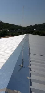
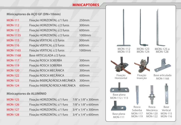
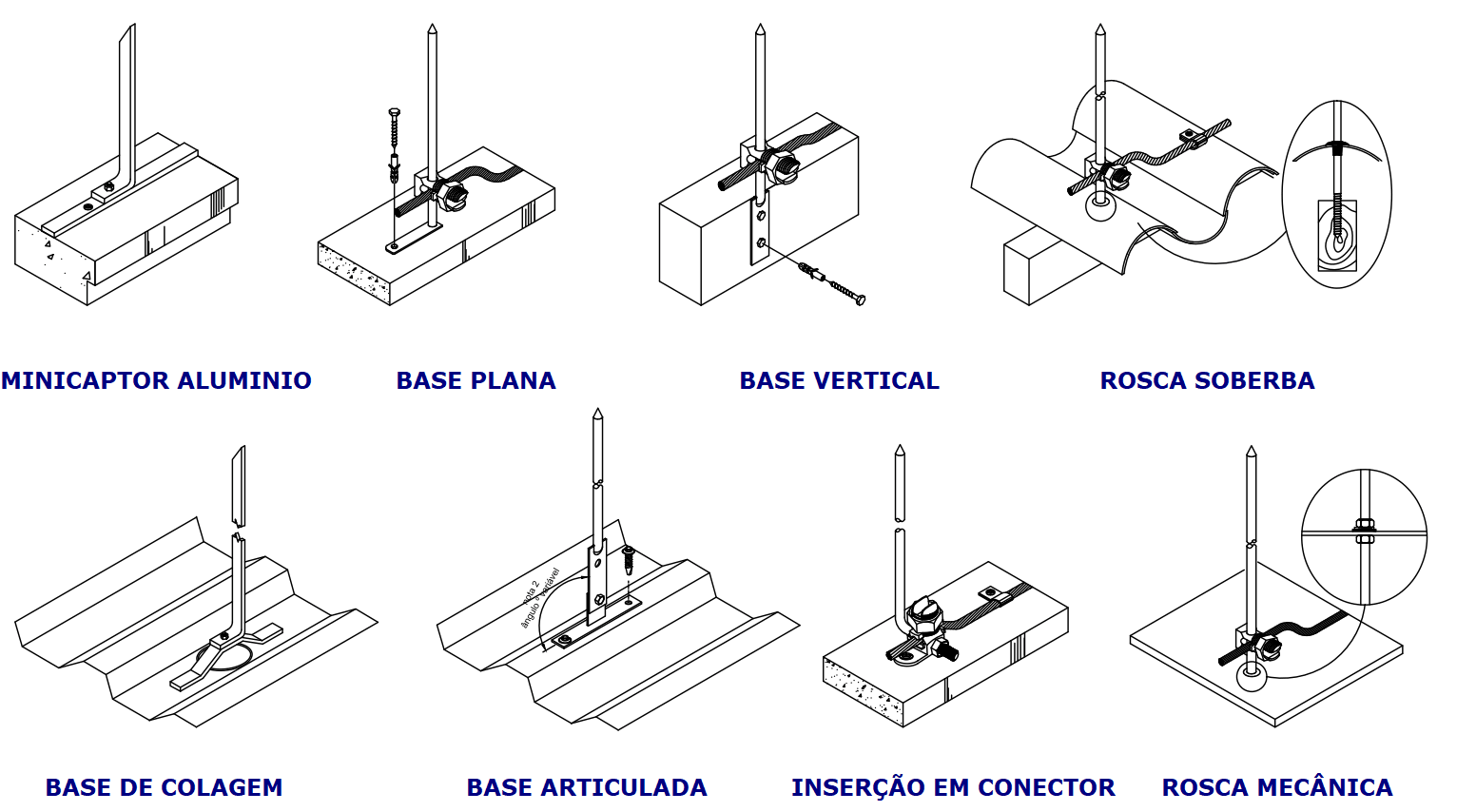
Minicaptors have the function of facilitating the reception of lightning, being the preferred point of impact of lightning on the roof of a structure. For adequate protection of a surface, correct sizing is very important, so as not to create unprotected areas due to inadequate spacing. The sizing can be done by the ELECTROGEOMETRIC / ROLLING SPHERE method provided for in ABNT NBR-5419/15.
In order to facilitate and speed up the specification / quantification of mini sensors, MONTAL developed, based on the standard, a simplified sizing table considering the height of the mini sensors manufactured by us.
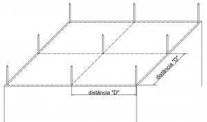
SIZING: This table is useful for large areas, such as shed roofs, but can be applied to any structure. The minicaptors must be on the same level and electrically continuous with each other by conductors or natural metallic element, according to NBR-5419/15 parameters.
“D” DISTANCE BETWEEN MINI CAPTORS – metros
CLASS OF SPDA | MINI CAPTOR HEIGHT (mm) | |||
| 250 | 300 | 600 | 1000 | |
| I | 4,3m | 4,7m | 6,8m | 8,7m |
| II | 5,3m | 5,8m | 8,3m | 10,7m |
| III | 6,5m | 7,2m | 10,2m | 13,2m |
| IV | 7,5m | 8,3m | 11,8m | 15,3m |
TECHNICAL DOCUMENT
SUBJECT: SELF-SUPPORTED POSTS
SPECIFICATION:
Product:
Hot dip galvanized steel pole
Popular name:
Franklin pole
Manufacture:
Montal Facilities Industry and Commerce Ltd.
Types and features:
|
| CLEARANCE | WEIGHT APPROX. |
MON-140 | Hot-dip galvanized steel pole 7 free meters, consisting of 2 modules, 2” (6m) and 1.1/2” (3m). | 7m | 33 Kg |
MON-141 | Hot-dip galvanized steel pole 10 free meters, consisting of 2 modules of 6m, 2.1/2” and 2”. | 10m | 67 Kg |
MON-142 | Hot-dip galvanized steel pole 12 free meters, consisting of 3 modules, 2.1/2” (6m), 2” (6m) and 1.1/2” (3m). | 12m | 75 Kg |
MON-143 | Hot-dip galvanized steel pole 15 free meters, consisting of 3 modules of 6m, 3”, 2.1/2” and 2”. | 15m | 98 Kg |
MON-144 | Hot-dip galvanized steel pole 17 free meters, consisting of 4 modules, 3″ (6m), 2.1/2″ (6m), 2″ (6m) and 1.1/2″ (3m). | 17m | 106 Kg |
MON-145 | Hot-dip galvanized steel pole 20 free meters, consisting of 3 modules of 6m, 4”, 3”, 2.1/2” and 2”. | 20m | 160 Kg |
Note: Accessories such as Franklin captor, rod, terminals, which appear in the attached drawing are not included with the product, and must be purchased separately.
Unit to order: Part.
INSPECTION, STORAGE AND INSTALLATION:
Visual Inspection: Upon receiving the product, check the quantity and diameter of the modules of each post according to the “types and characteristics” table. If any difference is identified, contact the supplier upon receipt of the invoice.
Handling: The material must be handled by at least 2 men, with the use of protective equipment scraping gloves and boots with certification (CA) recommended.
Vertical Storage: The product can be stored vertically in a large place, with a minimum height of 6.5m (ceiling height), supported by a firm and structured wall that supports the weight of the material, without objects or elements within a radius of 6m, which can be reached in the fall case. In vertical storage, precautions must be taken with regard to mooring/fixation in order to avoid overturning/falling, which could warp the pole, rendering the product unusable.
Horizontal Storage: The product can be stored horizontally in a place with a flat floor, in which case the use of 5 wooden wedges, distributed one every 1.5 m, is recommended, respecting a maximum stacking of 2 tubes.
Validity: The shelf life of the pole is indefinite, respecting the conditions of handling, storage and installation, being also conditioned to the climate and other characteristics/atmospheric agents, which may accentuate the rust/corrosion process, despite the hot dip galvanizing of the product being carried out to ensure long-term rust protection of steel. The pole must undergo periodic inspections/maintenance as provided for in item 6 of NBR-5419.
Installation: It must be carried out by a specialized company. Recommendations/general care during installation:
-Adapt the Franklin captor to the end of the pole before lifting/installation.
-The pole must be fixed in the ground, in a hole with a diameter of 50cm with a depth proportional to that specified in the technical drawing or up to a level marked with black tape at its base. The post must be centered in this hole and then prepared concrete can be poured in the mix of 1 bag of cement, 2 carts of sand and 1 cart of gravel. Stones can be thrown into the concrete or bottom of the pit.
-At ground level, the pipe is more vulnerable to moisture and corrosion. Concrete should be applied around the tube in a conical shape to facilitate drainage at a height of 10 cm.
-It is indicated that the pole is lifted from a point above its half, this lifting point always being a maximum of 50cm below the splice sleeve.
-The continuous swinging of the pole during the lifting process can warp it, and ropes must be used in several directions that can be tensioned during the process in order to interrupt the continuous swinging.
Note: Illustrative technical detail. Special measures of height, trespass,
fixing depth, diameter and sequence of tubes may differ from the drawing above.
TECHNICAL DOCUMENT
SUBJECT: AERIAL OBSTACLE SIGNALING – SUMMARY
TOPICS: Introduction / Synthesis for turrets
I
– INTRODUCTION:
This summary guide was prepared with the aim of assisting users of structures that need signage on the basic design criteria, based on the ordinance of the Ministry of Aeronautics that deals with the subject. Montal has a more complete document that deals with this subject, and interested parties should contact us to make it available.
We seek to elucidate the content of the ordinance, in a summarized document, being indicated to those interested in deepening the subject to consult and investigate with COMAR (Regional Air Commands), DAC – Department of Civil Aviation, Regional Services (SERAC, SERENG and SRPV) – bodies from the Ministry of Aeronautics or the City Hall of your municipality for better guidance.
The signaling has the purpose of reducing the dangers for the aircraft, indicating the presence of obstacles.
II – SYNTHESIS FOR THE APPLICATION OF SIGNALS IN TOWERS*
| For chimneys, electricity towers and overhead cables, there are other details to be consulted, including ABNT standards. | ||||
light class | Color | Code/model | Obs. | applies to |
| Low Intensity – fixed | red | Fixed light for fixed objects. minimum 10 cd | – Obstacles that are not extensive – Height less than or equal to 45 meters – In combination with other medium-sized items. | |
| Low Intensity – flashing 60 to 90 per minute | yellow or red | other obstacles (mobile) minimum 10 cd | ||
| Medium Intensity – flashing 20 to 60 per minute | red | geral >1600 cd | – Extensive obstacles – Height greater than 45 meters and less than 150 meters. – In combination with other low/high intensity. | |
| white | When used in conjunction with high-intensity light. >1600 cd | |||
| High Intensity – flashing 40 to 60 per minute | white | 200,000 day cd 4000 night cd(± 25%) | – Height greater than 150 meters – Elevated power line towers can reduce by 50% (see the content of ordinance 1141) |
MONTAL is not responsible for the content or subsequent changes to the ordinance that supported this document, encouraging interested parties to consult the bodies of the Ministry of Aeronautics or the City Hall of their municipality for better guidance.
File |
Format | Size | Download |
| Structural SPDA Structural protection system against Atmosferic discharges | PDF | 1.06 Mb |
| STRUCTURAL SPDA: Rebar Rebar and Mounting Structural Connector |
| INTRODUCTION |
| The steel hardware of the reinforced concrete structure of buildings began to be used as an efficient disperser of the lightning current, from the edition of NBR-5419 in 1993. In the LPS structural system, it is necessary to guarantee the electrical continuity and equipotentialization of the various parts of the structure, from the foundation to the top of the building. For this, as a safe, reliable and practical way to ensure regulatory requirements, ensuring adequate electrical continuity, additional hot-dip galvanized rebar RE-BAR and MONTAL Structural Connector are adopted, along with specific connection and tying procedures.Further ahead, in the HOW TO EXECUTE item, we provide technical information, according to Annex D of NBR-5419, which aims to facilitate the understanding of the structural system, not replacing, however, the official SPDA project. Ideally, the work should start with a specific SPDA project made responsible by an engineer registered with CREA. |

| Code | Description and dimensions | Application |
| MON-238 | Hot dip galvanized rebar 50mm²x4m (ø8mm) | Cornerstone |
| MON-239 | Hot dip galvanized rebar 80mm²x4m (ø10mm) | Foundation/Pillar |
| MON-240 | Hot dip galvanized rebar 3/8″x3m (ø70mm²) | Cornerstone |
| MON-241 | Hot dip galvanized rebar 3/8″x3.4m(ø70mm²) | Cornerstone |
| MON-432 | Galvanized clips for splicing bars ø 3/8″ | Rebar amendment |
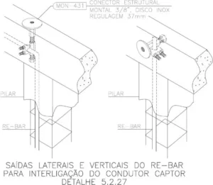
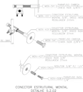
| MON-431 | MONTAL structural connector, 3/8″ thread, stainless steel disc, 37mm adjustment | Embedded in concrete |
| MON-427 | Tinned brass slotted screw connector with pigtail and 3/8″ mechanical thread for cables from 16 to 70mm² | Connection of conductors |
| MON-508 | INOX flat head screw 1/4″ x 7/8″ | On Prisoner MON-542 |
| MON-541 | 3/8″ x 1″ stainless steel flat head screw | In the structural connector |
| MON-542 | Stud reducer 3/8″ to 1/4″ | In the structural connector |
| HOW TO RUN |
| GROUNDING IN THE FOUNDATION: |
|
| DESCENTS ON THE PILLARS: |
|
|
| IMPORTANT: |
|

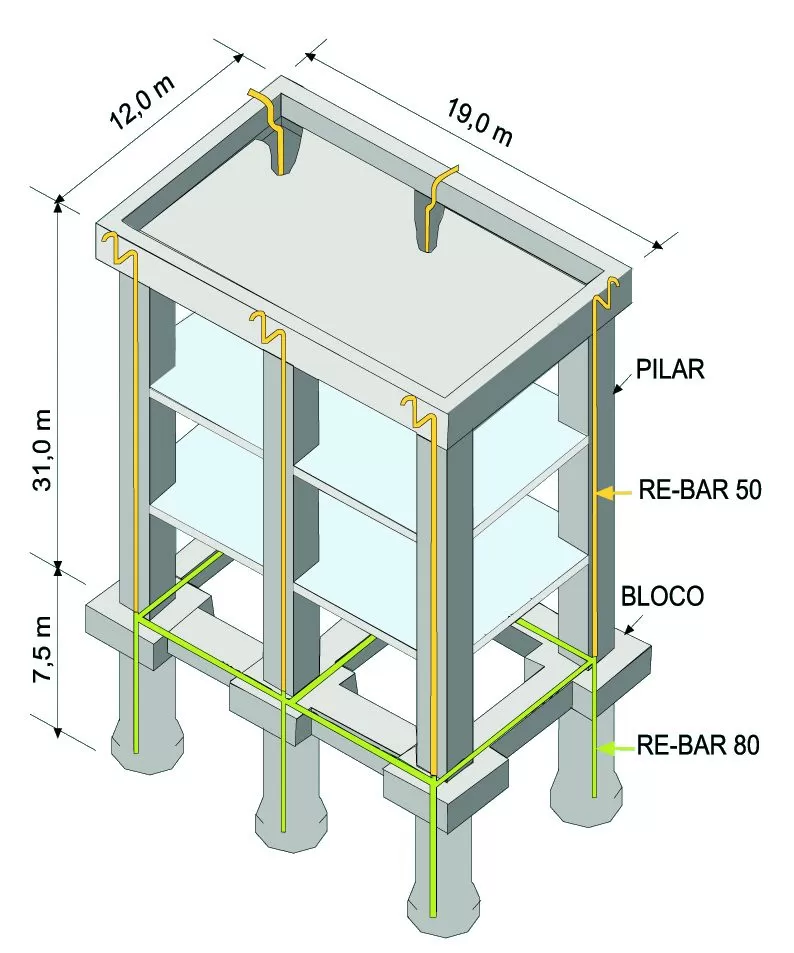
| On the side we present a figure of the structure of a building with STRUCTURAL SPDA. We will carry out a basic survey of the quantities of RE-BAR rebar and the respective clips. We remind you that it is always recommended to provide for extra bars as a safety procedure, since it is common for deviations to occur in the path of the pillars, external interconnection points, as well as “L” type pieces in the mooring (see detail B in the guidance guide on the back of this prospectus ). |
Grounding to the foundation (RE-BAR 80): Pipes: 6 pipes x 7.5 m deep = 45m Baldrame beam (cement): 12+12+19+19 = 62m Total: 45+62 = 107÷3.8* = 28 RE-BAR 80mm²x4m 3/8″ galvanized clips = 28 x 3 = 84clips Descents on Pillars (RE-BAR 50 or 3/8”): 6 pillars x 31m = 186m
Total: 186÷3.8m* = 49 RE-BAR 50mm²x4m Galvanized 3/8″ clips = 49 x 3 = 147 clips External connection 6 connections with intake + 6 connections at the base of the pillars on the ground floor+ 2 equipotential connections (ground floor and 6th floor.) = 14 MONTAL Structural Conctors – MON-431
Summary RE-BAR hot dip galvanized rebar 80mm²x4m – 28 pieces RE-BAR hot dip galvanized rebar 50mm²x4m – 49 pieces Galvanized 3/8″ Clips – 231 pieces MONTAL Structural Conctors – 14 pieces *despite the bar having 4m, it is considered in the calculation 3.8m, because it is lost 20cm for splicing each bar. |
| DETAILS FOR PROJECTS |
| We provide a library of technical installation details for our products free of charge on our website for use in project drawings.Check the catalog “full version” or “most used details”. The details regarding the STRUCTURAL SPDA are in the CadDetails section, item 5.2. Below are some examples of available details. |
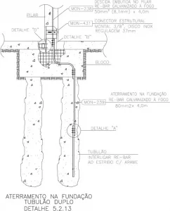
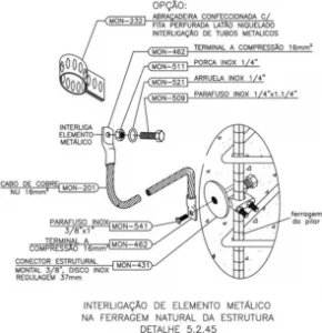 .
. 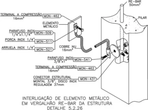 .
.  .
. 
TECHNICAL DOCUMENT
SUBJECT: GROUNDING OF FENCES IN RURAL AREAS
TOPICS: Introduction / Solution
I – INTRODUCTION: A storm cloud can charge wire fences with static electricity. Cattle that touch the fence will act as a ground wire, conducting the current from the fence to the ground, which will pass through its body, potentially causing the animal’s death. For this reason, it is important to discharge static electricity accumulated in the fence wires through grounding.



II – SOLUTION: The grounding of the fences must be done at least every 40 meters, interconnecting the wires of the fence with each other and connecting the interconnecting wire to a rod or grounding mesh. To reduce accumulated electricity, it is convenient to section the fence every two or three groundings. The figure below shows how this sectioning should be done, which can be done in three ways:
– Using special insulators;
– Using 30 to 50 cm pieces of wood, fixing the interconnection and grounding wires at their ends.
– Interrupting the fence, place two posts 30 to 50 cm apart and ground each section on the corresponding post.

The condition of the rods must be checked periodically (2 to 3 years), as there may be corrosion and the ground wire may become loose.
Consult our technical department to indicate the material suitable for this type of grounding.
TECHNICAL DOCUMENT
SUBJECT: RADIOACTIVE LIGHTNING ARRESTER
TOPICS: Introduction / Resolution CNEN/04/09 / Identifying a Radioactive Lightning Arrester / Removal and Packaging Procedures / Shipping and Transport
I – INTRODUCTION:
The manufacture of radioactive lightning rods in Brazil began in 1970. After 19 years, the National Commission for Nuclear Energy (CNEN), established, through Resolution 04/89, the suspension of the granting of authorization for the use of radioactive materials in lightning rods -rays.
It was believed that such lightning rods had the ability to attract lightning at great distances from the place where it was installed. However, after laboratory tests and simulations, it was technically proven that the attraction provided by these captors was identical to any metallic element or any other captor devoid of radioactive material, which resulted in the publication of resolution 04/89.
II – RESOLUTION CNEN/04/09
(Published in the D.O.U. on 05/09/89)
“Considering that the trade in radioactive substances constitutes a Union monopoly, instituted by Law No. 4,118, of August 27, 1962, article 1, item II, in fine.
Considering that this monopoly is exercised by CNEN as the supervisory body for guidance, planning, supervision and inspection.
Considering that CNEN is also responsible for registering people who use radioactive substances, as well as receiving and depositing radioactive waste.
Considering the proliferation of the use of radioactive substances in lightning rods.
Considering that the greater effectiveness of radioactive lightning rods in relation to conventional ones has not been technically proven and that, therefore, the “principle of justification” provided for in standard CNEN-NE-3.01-
“Basic Radiation Protection Guidelines” is not demonstrated. Considering the need to properly dispose of radioactive material from deactivated lightning rods. RESOLVES:
1- Suspend, as of the validity of this resolution, the granting of authorization for the use of radioactive material in lightning rods.
2- The remaining radioactive material from the deactivated lightning rods must be immediately collected from CNEN.
3- This resolution enters into force on the date of its publication.”
III – IDENTIFYING A RADIOACTIVE LIGHTNING ARRESTER
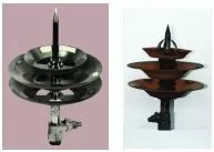
The most common characteristics of this type of sensor, considering the most commercialized brands in Brazil at the time (Gamatec, Amerion), are the shape composed of a kind of metallic discs arranged in parallel with small plates (2x4cm approximately) of radioactive material Am (Americium- 241) alpha emitter with a half-life of 432 years. Once these characteristics are identified, the captor must be removed according to appropriate procedures. |
IV – REMOVAL AND PACKAGING PROCEDURES
Simplified procedures that, without escaping the rigor of security, allow the safe operation of packaging and transport to the various CNEN facilities, for storage:
1- Use, as appropriate, one or more resistant metal packages, with a minimum capacity of 38 liters and with a closing system that guarantees the sealing of the package during transport (one lightning rod per package);
2- Have available gloves, plastic bag, adhesive tape, a label with the words “Radioactive Material”, shock absorbing material (fragmented Styrofoam, for example) and transport documentation (available at CNEN);
3- Uniformly place a layer of shock-absorbing material at the bottom of the packaging;
4- Place the plastic bag, open, inside the package;
5- Put on the gloves;
6- Remove the rod from the lightning rod and place it inside the package;
7- Remove the gloves, also placing them inside the plastic bag;
8- Close the bag, using adhesive tape;
9- Keep the lightning rod, already inside the bag, in the center of the package, filling in the empty spaces with shock absorbing material;
10- Affix the label with the words “Radioactive Material” inside the package, in a visible place when opening it;
11- Close the packaging.
V – SHIPPING AND TRANSPORT
Complete the transport documentation with the data relevant to the issuing institution. Previously contact the CNEN unit that will be able to receive the package(s), namely:
• Central Unit – Headquarters – Rua Gal Severiano, 90 – Botafogo – Rio de Janeiro – RJ – Brazil – CEP 22290-901
• Phone: (21) 2173-2000/ 2173-2001 – Fax: (21) 2173-2103 – http://www.cnen.gov.br
• Institute of Nuclear Engineering – IEN – University City – Ilha do Fundão – Rio de Janeiro – RJ – Brazil
• CEP 21945-970 – Tel.: (021) 2209-8065 – Fax: (021) 2590-2692
• Nuclear Technology Development Center – CDTN – Av. Presidente Antônio Carlos, 6627 – UFMG – Pampulha – Belo Horizonte – MG – Brazil – CEP 31270-910 – Tel.: (31) 3069-3241 – Fax.: (31) 3069-3321
• Institute for Energy and Nuclear Research – IPEN – Travessa R, 400 – Cidade Universitária – São Paulo – SP – Brazil – CEP 05508-900 – Tel.: (011) 3816-9095 – Fax: (011) 3212-3546
• Central-West Regional Center for Nuclear Sciences – CRCN-CO – BR 060, km 174.5 – Goiás Abbey – GO – Brazil – CEP 75345-000 – Phone: (62) 3604-6000 3604-6001 3604- 6002 Fax: (62) 3604-6020
• Northeast Regional Nuclear Sciences Center – CRCN-NE – Av. Prof. Luiz Freire, 200 – Cidade Universitária – Recife – PE – Brazil – CEP 50740-540 – Phone: (81) 3797-8000 – Fax: (81) 3797-8072
• District of Caetité – DICAE – Avenida Santana, nº 680, Centro – Caetité – BA – CEP 46400-000 – Phone: (77) 3454 2344 – Fax: (77) 3454 2333
• Fortaleza District – DIFOR – Av. Dom Luis, 880 – Rooms 1001-1004 – Aldeota – Fortaleza – CE – Brazil – CEP 60160-230 – Tel.: (85) 2364-3111 – Fax: (85) 3246-4033
• Brasilia Office – ESBRA – SCN, Block 4, Block B, Room 1002-B, Ed. VARIG – Asa Norte – Brasília – DF – Brazil – CEP 70714-900 – Phone: (61) 3327-2355 – Fax: (61) 3327-2228
• Porto Alegre office – ESPOA – Av. Bento Gonçalves, 9500 – Building 43322 – ILEA – Porto Alegre – RS – Brazil – CEP 91501-970 – Tel: (51) 3316-6942 / 3322 4995 – Fax: (51)33222455
• Poços de Caldas Laboratory – LAPOC – Poços de Caldas Highway, km 13 – Andradas – Poços de Caldas – MG – Brazil – CEP 37701-970 – Tel: (35) 2107-3500 – Fax: (35) 3722-3622
Annex G
Safety procedures for risk reduction outside the structure
This document is a summarized didactic adaptation of Annex G of NBR-16785, focused on models of conduct and information that guide actions with the aim of reducing the risks caused by lightning in open areas.
There are no means to prevent lightning strikes. However, by following some elementary rules, people can protect themselves against its harmful effects.
Atmosferic discharges
Characterized by very high energy acting in milliseconds. Consequently we have several effects: thin conductive wires melt and objects are heated so strongly that they can ignite or explode. If the lightning current finds a path through a structure containing moisture, such as damp walls, beams, roofs or trees, this path can suddenly explode. Lightning currents can penetrate structures through power and signal lines (TV cable for example), damaging electrical and electronic equipment and causing electric shock and possible injury.
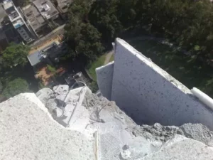
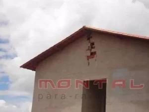
Figure 1 – Lightning destruction image
In open areas, people are susceptible to direct discharges (especially when they are standing), lateral discharges, induced discharges, touch and step voltages.
Direct lightning strikes:
Being hit by direct lightning strikes (see Figure 2) is the most dangerous threat when it comes to lightning strikes. Lightning current flows through the person and causes unconsciousness, internal and external burns, apnoea, cardiac arrest or paralysis.
Figure 2 – Direct Discharge
It is recommended that unprotected structures are not used as shelters, especially small isolated structures such as bus stops, small canopies or small buildings (kiosks, barns, warehouses, huts). Structures with metal roofs and non-metallic supports can accentuate the effects of lightning.
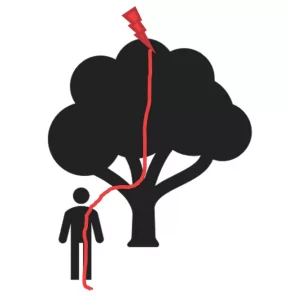

Figure 3 – Lateral Discharge Figure 4 – Sparking in metallic structures not suitable for protection
Touch or contact voltages: Metal structures not only pose a threat due to arcing resulting from an induced voltage, but also due to touch or contact voltages. To reduce the risk of electric shock due to touch voltages, it is recommended to stay away from potential lightning current carriers when the storm is in the vicinity. Electrification by touch voltages (or contact voltages) occurs when people, with their feet in contact with a sufficiently conductive and grounded surface, touch a conductive structure that may be at a different electrical potential due to a lightning strike (see Figure 5) .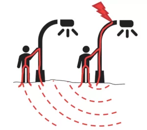
5) Touch voltage electrification
Step voltage: When lightning strikes the ground, the discharge current spreads through the various layers of the ground. A large increase in potential occurs at the point of impact. Step voltages can arise near this point. However, when the discharge strikes buildings, structures or trees, the discharge current flows to earth through the grounding devices of the buildings or structures, or through the roots of trees, and produces hazardous high potentials in the soil. Humans can experience dangerous pitch stress near buildings, structures, or trees.
People can suffer step stresses when they are standing with their feet apart or walking (see Figure G.6) and when lightning strikes the surroundings. This situation is more dangerous if the ground resistivity is higher, the distance to the point of impact is shorter and/or the distance between the two feet is greater.

THIS ARTICLE REMAINS IN THE FILE AVAILABLE FOR DOWNLOAD WITH THE FOLLOWING TOPICS: